


Centrifugal pumps.A clear path
to selection.
Explore 13 pump configurations. Understand the arrangement, compare the type codes, then define the hydraulic duty and project requirements with engineering.
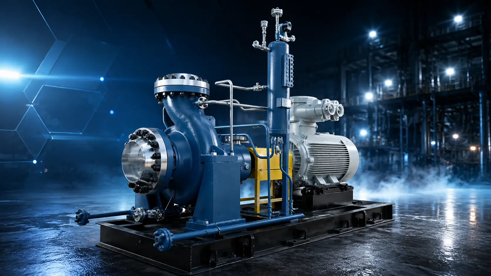
Three families. Different constructions.
The type code describes the mechanical configuration. Hydraulic sizing also depends on flow, head, fluid properties and suction conditions.
Overhung
The impeller is supported outboard of the bearing arrangement. Horizontal and vertical inline designs differ in mounting, bearings and coupling.
Explore OH configurations ↓Between bearings
The impeller or impeller group is supported between bearings. Casing split, stage count and pressure-boundary construction distinguish the types.
Explore BB configurations ↓Vertically suspended
Vertical arrangements place the hydraulic assembly below the support. Column, discharge and casing construction distinguish the configurations.
Explore VS configurations ↓Find a type. Understand the difference.
 View full-size image ↗
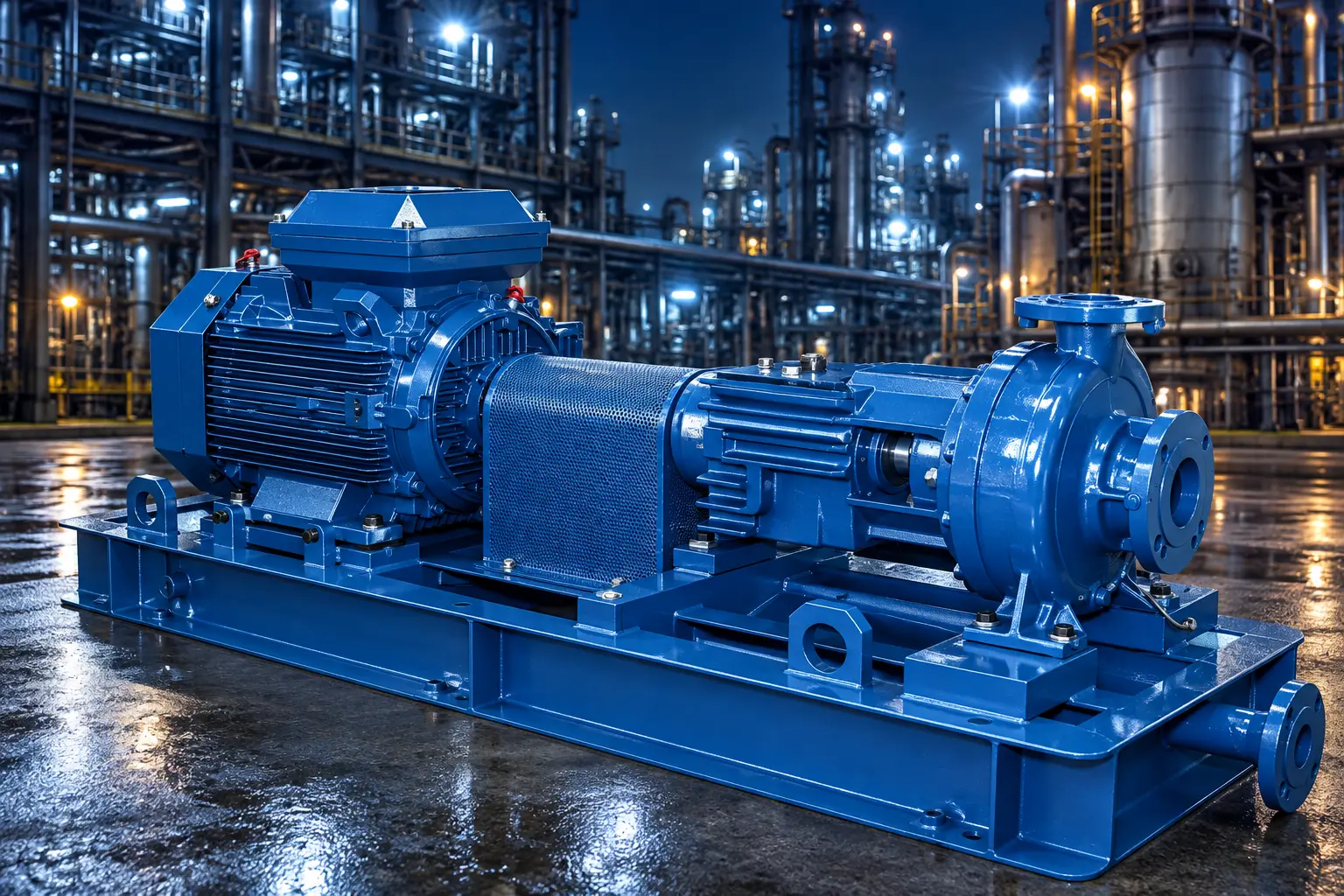
OH1
Horizontal, single-stage overhung pump with foot support and a flexible coupling.
Technical arrangement & selection notes
- Arrangement
- Horizontal overhung
- Construction
- Foot-mounted
- Stages
- Single stage
Review operating temperature, piping loads and the project’s acceptance of the proposed mounting arrangement.
 View full-size image ↗
OH2
Horizontal, single-stage overhung process pump supported at the casing centerline.
Technical arrangement & selection notes
- Arrangement
- Horizontal overhung
- Construction
- Centerline-mounted
- Stages
- Single stage
Confirm hydraulic coverage, suction margin, seal system, driver and material selection for the specified fluid.
 View full-size image ↗
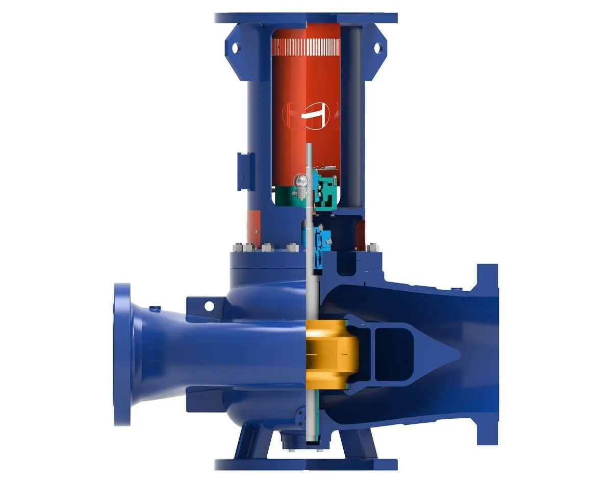
OH3
Vertical inline overhung pump with its own bearing housing and a flexible coupling to the driver.
Technical arrangement & selection notes
- Arrangement
- Vertical inline
- Construction
- Separate bearing housing
- Stages
- Single stage
Review support, nozzle loads, maintenance access and the specified coupling and bearing arrangement.
 View full-size image ↗
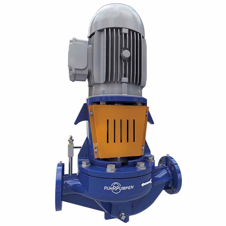
OH4
Vertical inline overhung pump with a rigid coupling between the pump and driver shafts.
Technical arrangement & selection notes
- Arrangement
- Vertical inline
- Construction
- Rigidly coupled
- Stages
- Single stage
Confirm the driver, thrust-bearing arrangement and project requirements for this coupling configuration.
 View full-size image ↗
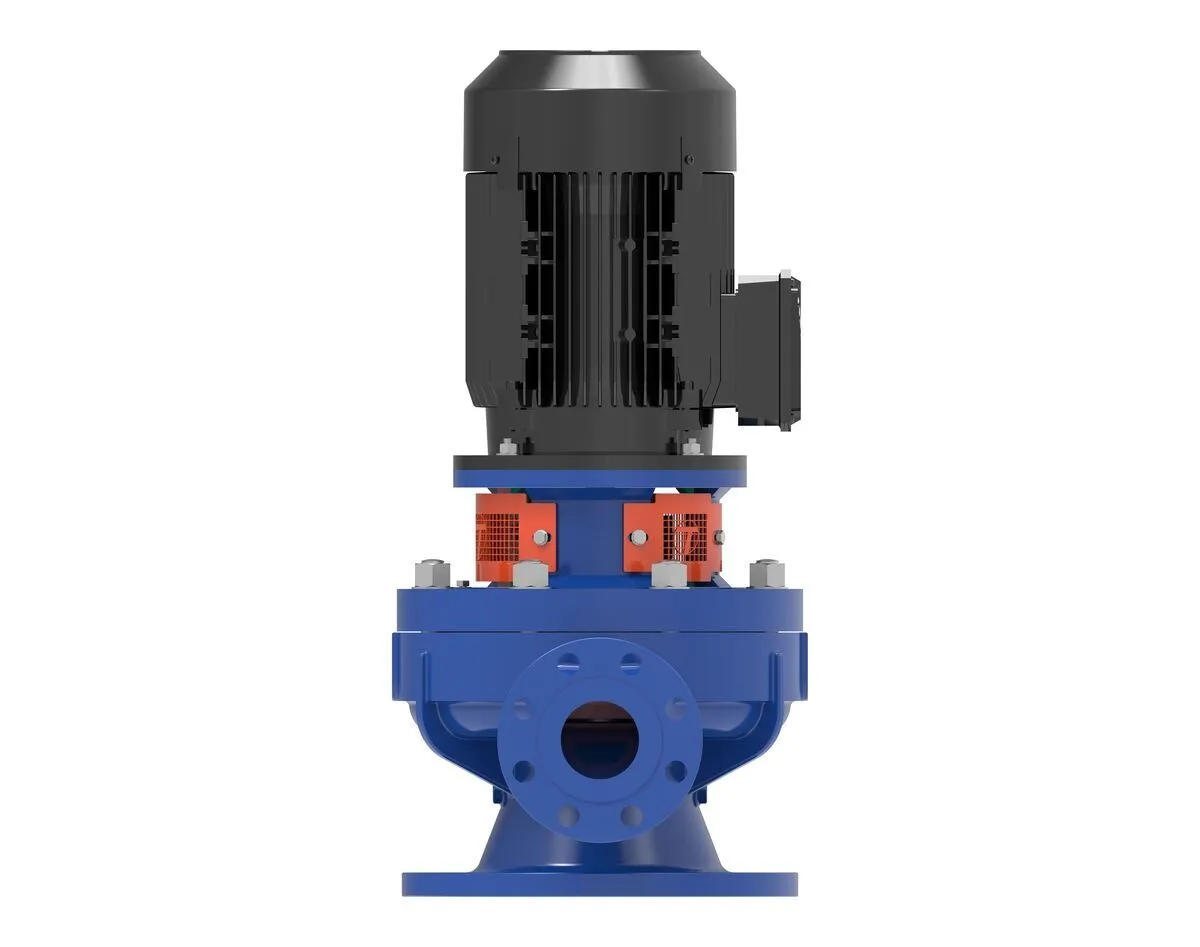
OH5
Vertical inline overhung pump with the impeller mounted on the driver shaft.
Technical arrangement & selection notes
- Arrangement
- Vertical inline
- Construction
- Close-coupled
- Stages
- Single stage
Confirm driver-shaft details, bearing loads, temperature limits and the project’s acceptance of this arrangement.
 View full-size image ↗
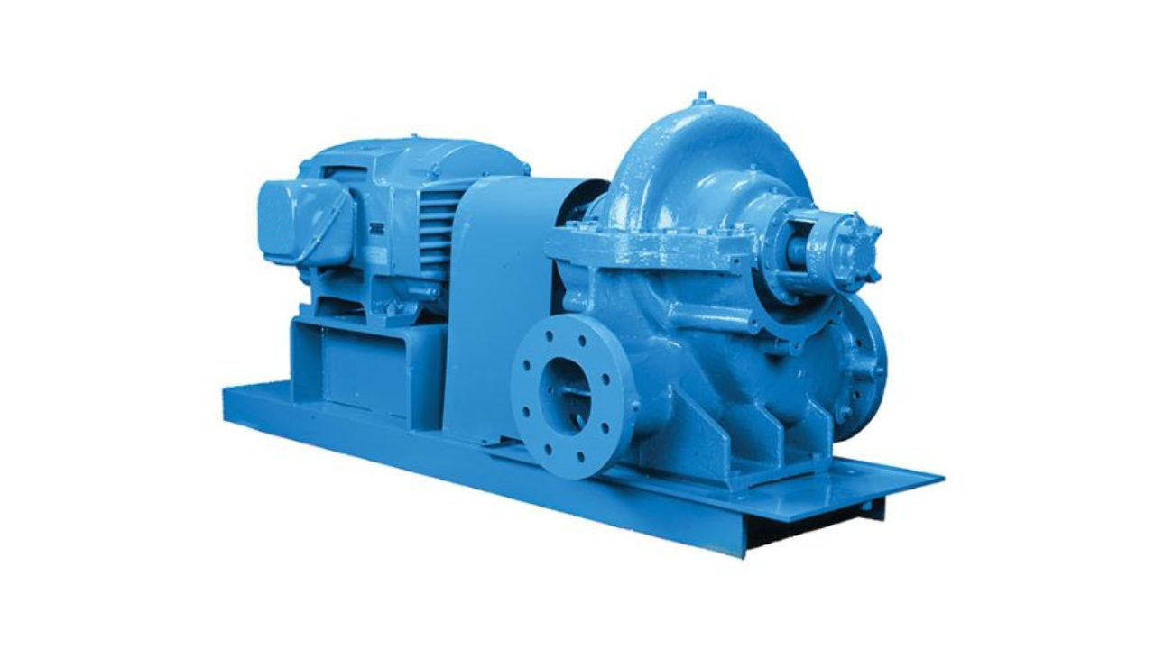
BB1
Between-bearings pump with an axially split casing, in single- or two-stage arrangements.
Technical arrangement & selection notes
- Arrangement
- Between bearings
- Construction
- Axially split
- Stages
- One or two stages
Specify the required head, flow range, suction conditions and casing arrangement before selecting a hydraulic size.
 View full-size image ↗
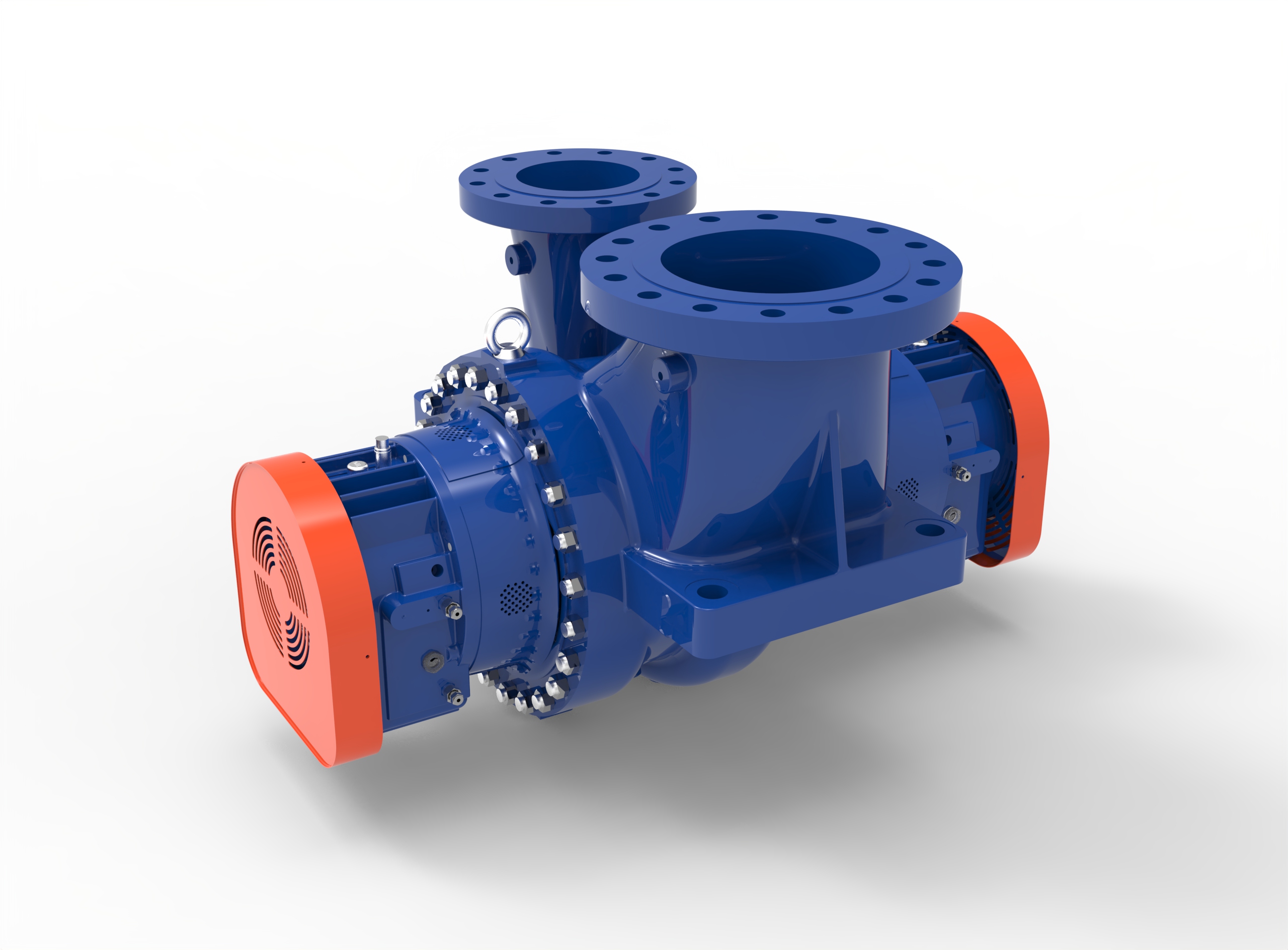
BB2
Between-bearings pump with a radially split casing, in single- or two-stage arrangements.
Technical arrangement & selection notes
- Arrangement
- Between bearings
- Construction
- Radially split
- Stages
- One or two stages
Confirm pressure and temperature conditions, stage arrangement and maintenance requirements for the selected design.
 View full-size image ↗
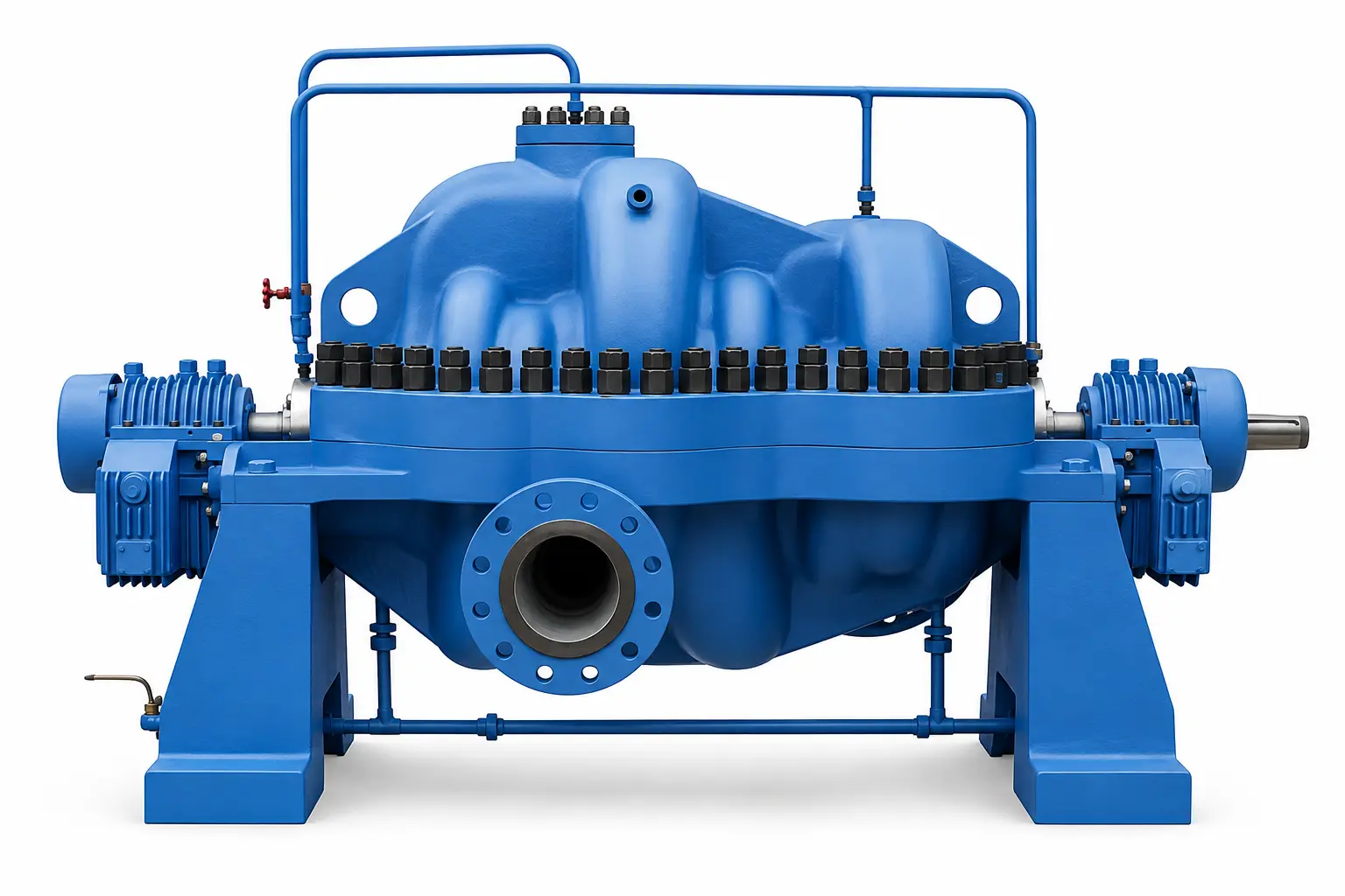
BB3
Multistage between-bearings pump with an axially split casing.
Technical arrangement & selection notes
- Arrangement
- Between bearings
- Construction
- Axially split
- Stages
- Multistage
Review the duty range, rotor dynamics, axial-thrust balance and inspection requirements against the project specification.
 View full-size image ↗
BB4
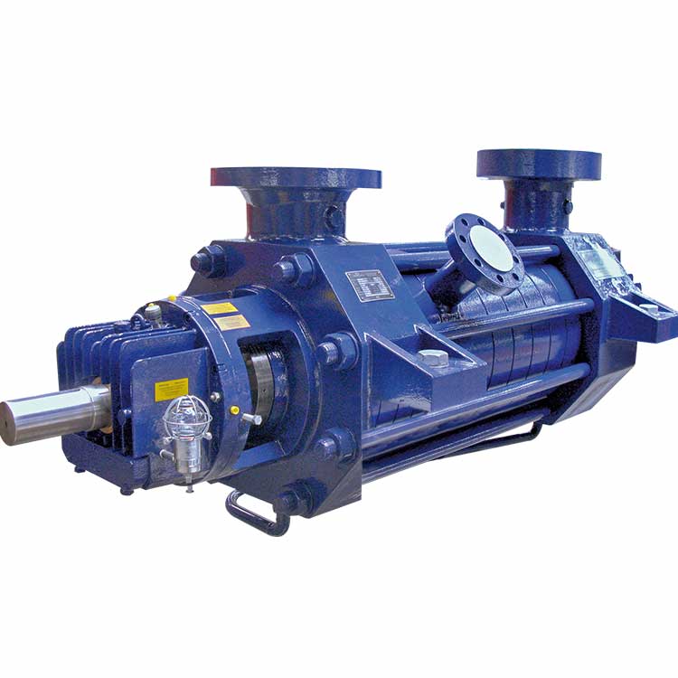
Multistage, radially split, single-casing between-bearings pump, commonly in ring-section construction.
Technical arrangement & selection notes
- Arrangement
- Between bearings
- Construction
- Single casing · radially split
- Stages
- Multistage
Confirm stage count, pressure boundary, rotor support and axial-thrust balancing for the required operating envelope.
 View full-size image ↗
BB5
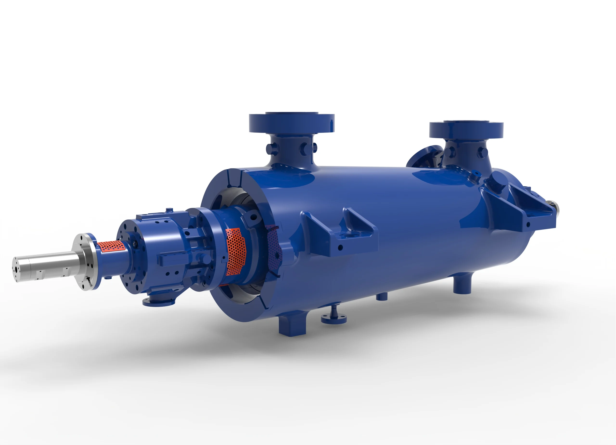
Multistage, radially split, double-casing between-bearings pump with an outer barrel.
Technical arrangement & selection notes
- Arrangement
- Between bearings
- Construction
- Double casing · barrel
- Stages
- Multistage
Review the pressure envelope, cartridge maintenance access, rotor arrangement and agreed testing scope.
 View full-size image ↗
VS1
Vertically suspended diffuser pump with a single casing and discharge through the column.
Technical arrangement & selection notes
- Arrangement
- Vertically suspended
- Construction
- Single casing · diffuser
- Stages
- To selected hydraulic design
Confirm minimum liquid level, submergence, intake conditions, column length and available NPSH.
 View full-size image ↗
VS4
Vertically suspended, single-casing line-shaft pump with a separate discharge pipe.
Technical arrangement & selection notes
- Arrangement
- Vertically suspended
- Construction
- Separate discharge pipe
- Stages
- To selected hydraulic design
Specify sump geometry, liquid levels, bearing lubrication and fluid properties, including any solids.
 View full-size image ↗
VS6
Vertically suspended diffuser pump with a double-casing, can-type arrangement.
Technical arrangement & selection notes
- Arrangement
- Vertically suspended
- Construction
- Double casing · can type
- Stages
- To selected hydraulic design
Review can depth, suction conditions, installation levels, venting and hydraulic requirements with engineering.
Type codes identify construction arrangements. An arrangement label alone does not establish full API 610 compliance. The proposed design, specified edition, deviations, materials and testing requirements must be agreed against the project specification. Images illustrate configurations; the order-specific general arrangement and datasheet define the supplied equipment.
Compare all 13 configuration types
Select a type code to locate its card. On smaller screens, scroll the comparison table horizontally.
| Type | Arrangement | Construction / mounting | Stages |
|---|---|---|---|
| OH1 | Horizontal overhung | Foot-mounted | Single stage |
| OH2 | Horizontal overhung | Centerline-mounted | Single stage |
| OH3 | Vertical inline | Separate bearing housing | Single stage |
| OH4 | Vertical inline | Rigidly coupled | Single stage |
| OH5 | Vertical inline | Close-coupled | Single stage |
| BB1 | Between bearings | Axially split | One or two stages |
| BB2 | Between bearings | Radially split | One or two stages |
| BB3 | Between bearings | Axially split | Multistage |
| BB4 | Between bearings | Single casing · radially split | Multistage |
| BB5 | Between bearings | Double casing · barrel | Multistage |
| VS1 | Vertically suspended | Single casing · diffuser | To selected hydraulic design |
| VS4 | Vertically suspended | Separate discharge pipe | To selected hydraulic design |
| VS6 | Vertically suspended | Double casing · can type | To selected hydraulic design |
Take the next engineering step.
Review the product information, explore available curve data, or send your operating conditions for a technical review.
Centrifugal pump catalog
Review the existing product catalog in PDF format. Ask engineering for the applicable curve, datasheet and general arrangement for your proposed duty.
Open centrifugal catalog · PDFStart with flow and head.
Explore the curves and pump candidates available in the selection tool. Curve coverage depends on the released data; final selection requires engineering confirmation.
Open pump selection softwareThe duty point is only part of the specification.
Include the operating envelope and fluid properties so the proposed configuration, hydraulic size, materials, sealing and drive can be reviewed together. Request the inspection, testing and material documentation needed for your project.
- Flow & differential headNormal, rated and expected operating range
- Fluid propertiesComposition, density, viscosity and solids
- Temperature & pressureOperating and design conditions
- Suction conditionsAvailable NPSH and minimum liquid level
- Materials & sealingCompatibility and site requirements
- Project requirementsDriver, standards, inspection and testing

West Karoon crude oil transfer.
A centrifugal pump reference from our project portfolio. Explore the portfolio for project descriptions, technical information and photographs.
Explore project references ↗Questions before selection.
How do OH3, OH4 and OH5 differ?
All three are vertical inline overhung arrangements. OH3 uses a separate pump bearing housing and a flexible coupling. OH4 uses a rigid coupling between pump and driver shafts. OH5 is close-coupled, with the impeller on the driver shaft. The bearing, coupling and driver arrangement should be reviewed against the project requirements.
What is the main difference between BB4 and BB5?
Both are multistage, radially split, between-bearings arrangements. BB4 has a single casing, commonly of ring-section construction. BB5 has a double-casing arrangement with an outer barrel. Pressure, temperature and maintenance requirements help define the appropriate design.
Can the configuration code determine flow, head or NPSH?
No. A type code identifies a mechanical arrangement. The flow, head, efficiency, power and NPSH requirements depend on the hydraulic model, impeller, speed, fluid and operating conditions. Use the applicable performance curve and an engineering review.
Ready to define your pump duty?
Send the operating conditions and project specification. Our engineering team can review the proposed configuration and technical scope.
Configuration terminology cross-checked against the Hydraulic Institute pump-type reference ↗. Project compliance is confirmed separately.